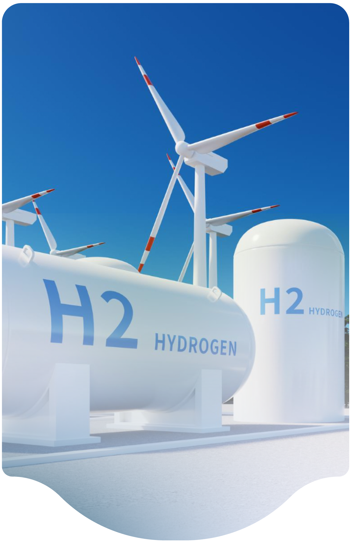
Electrolyzer

What guidance is available for using an autonomous solar hydrogen electrolyzer to produce and vent small amounts of hydrogen to the atmosphere, with a goal to eventually demonstrate compressing the hydrogen into a storage tank? Because solar is intermittent, there needs to be an operating scheme that keeps the unit running when power is low. The electrolyzer runs 24 hours per day, albeit with relatively low output.

The vent system for the excess hydrogen should be vented in accordance with NFPA 2 and CGA G-5.4 and G-5.5. The oxygen also must be vented safely and should be in accordance with NFPA and CGA G-4.4. 


Please be extremely cautious with compressing hydrogen. NEC/NFPA 70 and its Articles 500/505 address electrical equipment in flammable atmospheres. Please also consider the information in NFPA 2, Hydrogen Technologies Code. NFPA 2 has many prescriptive requirements for use, generation, and compression of hydrogen with properly rated equipment and containers. There have been many accidents where equipment and systems not rated for hydrogen have: 

  • leaked near ignition sources such as static electricity and standard electrical equipment, 
  • used vessels not intended for hydrogen, 
  • used vessels improperly purged of air or other reactive gases, and d) located equipment in areas with inadequate air ventilation that allows hydrogen to accumulate. 

Valuable insight comes from an incident that occurred in May 2019, where an outdoor hydrogen tank exploded at a research and development venture complex during test of a water electrolyzer coupled to a renewable energy system. The estimated 100 lb. TNT equivalent blast killed two and injured six. The cause of the tank explosion was reported to be auto-ignition of a hydrogen-oxygen gas mixture within the storage tank. The gas source, a 9 bar H2 and O2 rated pressurized alkaline water electrolyzer, was under test to evaluate intermittent renewable energy duty cycle performance. 

Technical reports state that potential electrolyzer cell membrane degradation permitted excessive oxygen gas crossover rate through the electrolyzer cell membranes into the product hydrogen gas. This condition may have been made worse by an extended period of low electrolysis gas generation rate prior to the incident, resulting in low hydrogen flow rates insufficient to dilute diffused oxygen below O2 in H2 flammability/explosibility limits. Corrective actions reported include use of catalytic gas purifiers to remove O2 from the product H2 and waste O2 lines.     

Lessons learned: 

  1. Understand interrelation of electrolyzer membrane gas permeability, membrane degradation, and dynamic operating range when establishing process safety controls; 
  2. Consider automatic gas storage isolation and stopping gas generation when safety limits are exceeded, such as flammable gas mixture, excessive cross-cell differential pressure, low dynamic range, and other applicable process safety limits.
     
FAQ Category
Submission Year
2024
Month
04

Venting System

Should a venting system be installed for the relief valves on backup cylinders of hydrogen gas in an outdoor storage/use area, as is done for the hydrogen venting system indoors?

Regarding cylinders, it is not necessary to capture the fuse-backed devices which are on the cylinder itself. However, all other relief devices and vent valves must exhaust from a vent system designed in accordance with CGA G-5.5. Also, note that NFPA 2-7.1.17 requires compliance with CGA G-5.5 regardless of storage quantity when the vent system is servicing pressure relief devices. Cylinders in storage that are capped and within an approved cylinder storage area do not require a vent system.

FAQ Category
Submission Year
2024
Month
04

Liquid Storage

Is liquid hydrogen storage possible within current codes/standards? Would any public fueling station realistically be able to fit liquid storage with current codes?

NFPA 2 has provisions for the use of LH2, and there are many existing fueling stations that store and use liquid hydrogen. One challenge for the use of LH2 in stations with small footprints is the code required separation distances from exposures. NPFA 2 has updated the separation distances with a risk informed approach in the 2023 edition.


Another possibility for public fuel stations would be to install the LH2 tank underground. Underground LH2 storage is permitted within NFPA 2 and requirements can be found in Section 8.3.2.3.1.7. It is certainly feasible to design and build a fuel station with an underground LH2 tank. 


It’s important to note that the NFPA definition of storage systems and resulting separation distance requirements are based on more than just the tank. The definition in NFPA 2 is an assembly of equipment that consists of, but is not limited to, storage containers, pressure regulators, pressure relief devices, vaporizers, liquid pumps, compressors, manifolds, and piping and that terminates at the source valve. The Hydrogen Tools portal (http://h2tools.org) has a variety of information, best practices, and lessons learned. 
 

FAQ Category
Submission Year
2024
Month
04

Equipment Spacing

How do equipment spacing and tank orientation requirements in standards such as Global Asset Protection Services 2.5.2 differ from / relate to NFPA 2?

The Global Asset Protection Services (GAPS) standard was written 20 years ago for property loss prevention at crowded chemical plants and is intended for existing and new oil and chemical facilities to limit explosion over-pressure and fire exposure damage; thus, the purpose is different than NFPA 2. NFPA distances were based on studies from the 1960s as well as qualitative factors that were deemed successful based on applied experience over the years. A risk informed approach as described within Annex E of NFPA 2 was applied to GH2 separation distances in the 2011 edition. These were further revised in 2020. Similar changes as described in Annex N of NFPA 2 were applied to LH2 distances in the 2023 edition.


These distances are based primarily on hydrogen piping releases as a function of pipe diameter and pressure. Exposures were aggregated into three groups and separation distances applied to each as applicable based on unignited vapor clouds, radiation exposure from jet fires, and overpressure. It’s important to note that many facilities have site specific issues such as large quantities, confinement, and congestion, so it may be applicable to apply contemporary engineering models to fully assess risk.
 

FAQ Category
Submission Year
2024
Month
04

Insulated Pipes

How can I estimate the life expectancy of liquefied hydrogen products (valve, instrument, tank, tank trainer, pump, piping, etc.)?

The lifetimes of these components will vary depending upon the application, their installation environment, and usage. It is also important to adhere to the component inspection, maintenance and replacement specifications as recommended by the manufacturer. However, as many are made of stainless steel, their life expectancy is longer than other materials. Estimated lifetimes are below in years: 
•    Liquid Hydrogen Tanks: 15-20 years between refurbishment but lifetime over 40 years is typical (tanks have lasted 40+yrs)
•    Ambient Vaporizers: 15-20 years
•    Pressure control Manifolds: 10-15 years
•    Cryogenic Liquid Pumps: 15-20 years but generally require annual maintenance for wear items
•    Valves instruments, etc.: 5-7 years but may require seal replacements depending on usage 
 

FAQ Category
Subscribe to System Design
We are professional and reliable provider since we offer customers the most powerful and beautiful themes. Besides, we always catch the latest technology and adapt to follow world’s new trends to deliver the best themes to the market.

Contact info

We are the leaders in the building industries and factories. We're word wide. We never give up on the challenges.

Recent Posts