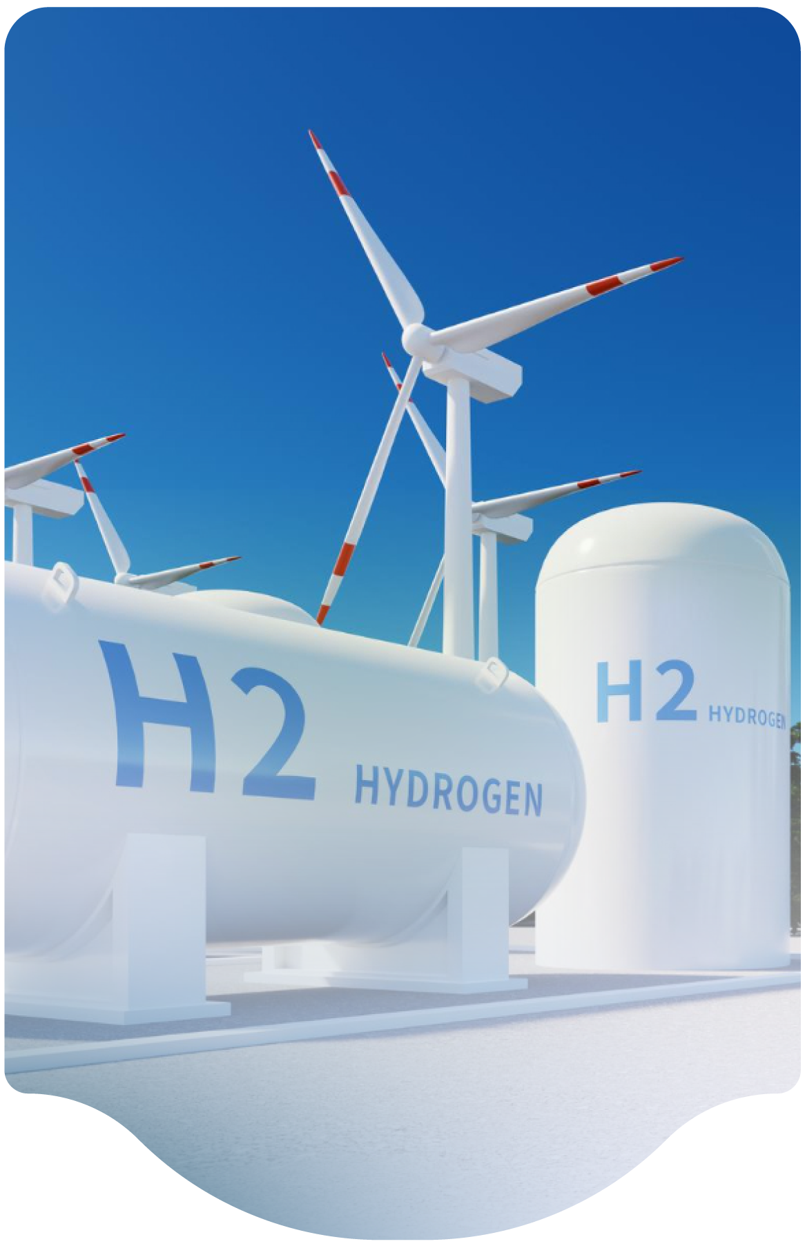
Electrical Classification Zone Around a Liquid Hydrogen System

Reference NFPA 2 TIA 1783: As we continue the update for next submission of our hydrogen safety plan, we received this TIA about hydrogen releases from LH2 bulk storage tanks and potential impact on venting and plume dispersion. I understand this was rejected by the NFPA 2 committee, but I wanted to engage the HSP to get feedback if this is something we should consider in our design for site layout for our coming liquid hydrogen dispenser to support our project. We are going to raise this topic in our HAZOP, but we are interested if the panel has experience on how to best assess our bulk storage tank and vent stack configuration for the site before we go too far down any path.

TIA 1783 points out a valid concern about how to address the electrical classification zone around a liquid hydrogen system. The existing requirements specify 3' around the outlet of the stack for Division 1 and 25' around the outlet of the stack for Division 2 area. These distances are historical and date back to the 1960's. They are a "one size fits all" simple approach that is easy to implement. Most existing systems use these distances for hazardous area plot plans and equipment selection. However, the distances are conservative for some systems, but also may not be sufficient for larger systems with higher flowrates.

These classified areas apply both to the system itself (for leaks) as well as the vent system outlets. This becomes more complicated since leaks are not expected, but may occur. In contrast, vent stacks are frequently used and hydrogen is expected to be vented since that is the stack’s function. Therefore, vent systems should be designed to properly vent the hydrogen to minimize impacts to personnel, facilities, and the environment.

The currently adopted editions of NFPA 2 are minimum requirements, but best practice for vent stacks would be to follow principles in NFPA 497 to ensure that the specific system and stack classified areas are developed with the actual parameters based on flow, direction, height, physical design, etc. The expected vent flows should be modelled and the classified areas developed accordingly, while using current NFPA requirements as a minimum for both the system and vents. NFPA 2 will eventually be updated with a new table in the future that is similar to, but not the same as, the proposal in TIA 1783.
 

BACKGROUND:
A Division 1 classified area expects hydrogen to be present for some portion of the time during normal operation. A Division 2 area only expects hydrogen to be present under upset conditions. Since systems are designed not to leak, and since leaks are not normal, the area around piping/tanks/etc. is normally considered Division 2. However, in certain areas such as fill connections and vent systems, hydrogen gas releases are expected. Hence, these areas are considered to be Division 1. The 3' extent of Division 1 area is somewhat arbitrary. A fill connection might have a small release of hydrogen during disconnection. Alternately, a vent stack could release much more substantial volume of hydrogen: a relatively small volume from normal operations to a very large release from a pressure relief device. TIA 1783 was correctly noting that since relief devices are of known sizes, then the classified areas should be based on the actual modelling of the relief rates and not just depend upon the traditional 3' or 25' distances.

For example, if it is known that a production system will vent a quantity that will result in a cloud that is 50' radius every time that it shuts down, then the classified area(s) should be much larger than the prescribed area. Similarly, if there is a very large relief device that isn't expected to operate, but might reasonably operate during the life of the system, then a similar analysis should be done.

TIA 1783 tried to express this in a new table but requires additional dialogue and analysis. Documents such as NFPA 497 (as referenced in the TIA), and API Standard 520 can be used as a best practice to develop the appropriate classified areas based on release rate models.

Classified areas are often shown in 2-D on drawings, but they are more accurately portrayed in 3-D (e.g. a "sphere"). In these situations, the height of a vent stack is a key dimension to ensure that the hydrogen cloud, radiation, and overpressure don't significantly create harm, especially considering hydrogen’s buoyancy. A properly designed vent stack should ensure that the momentum from the release further facilitates the upward direction from buoyancy, thereby reducing the extent of the classified area in the downward direction.

FAQ Category
Submission Year
2025
Month
02

Designing Vent Systems for High-Pressure Systems

We are currently working on an engineering project involving high-pressure hydrogen storage operating at high pressure. What are the best practices for designing vent systems for such high pressure? Specifically, how should we approach the scenario for a rupture disc or high flow for emptying the tubes to avoid unnecessarily large vent system piping?

It is best to avoid planned blowdown of large amounts of hydrogen inventory at high flowrates if possible.  Low flow releases from vent systems are normal and occur for purging, delivery operations, and maintenance activity.   A challenge with high flow blowdown of a hydrogen system is that venting large quantities of hydrogen can itself be a hazardous activity.   Large blowdowns at high rates from vent systems can lead to jet fires and explosions after release to the atmosphere.

Flaring can be an option.  However, if flare stacks are used, they must ignite before the hydrogen reaches the end of the vent stack, so that a delayed ignition of the hydrogen does not occur, as this could create damaging overpressure.   A flare system is a complicated design for hydrogen. It is not normally a best practice unless the timing of the release is always known, and the flare cannot be extinguished until the hydrogen flow is stopped. Flares are generally only used at large production facilities which have the necessary infrastructure. 

A best practice for any storage system is to site the storage vessels away from any flammable substances and/or protect the vessels with barriers or insulation. It’s inherently safer to avoid   fire exposure onto the vessels, especially since relief devices may not be well suited to protect a vessel in the case of an impinging fire.  Similarly, there may be other methods to limit the H2 released by reducing the size, type or quantity of safety devices on a storage system. 

A best practice, when the storage vessels are not subject to an engulfing fire, is to use reclosing safety devices, such as spring loaded or pilot operated safety valves.  These do not empty the entire contents of the tubes, but open just to maintain the pressure within design criteria. 

Where it may be impossible to completely eliminate engulfing fires, rupture discs or thermally activated pressure relief devices (TPRD) are often preferred since once they activate, they will continue to vent until all pressure is released.  This is important since the fire may weaken the vessel while still at the reclosing devices’ setpoint, causing a vessel failure and a large sudden release of its content. However, non-reclosing relief devices can also be prone to inadvertent or spurious activation.  This can result in unnecessary and unwanted releases which can cause hazardous situations from high reaction forces and large quantity of the release. 

FAQ Category
Submission Year
2025
Month
01

Toroidal rings may reduce static ignition risks in hydrogen vents, but dilution below flammable limits is more effective for mitigating vent stack fires.

Are there effective methods to prevent ignition of vented hydrogen streams from vents using toroidal ring designs?

There is some indication that toroidal rings can reduce static buildup and ignition of hydrogen from a vent. However, while toroidal rings may help with static, they have not been proven to eliminate all static ignition sources. There are also other sources of ignition that they would not prevent, so they might reduce but not eliminate, vent stack fires. Another method that can be reliably used to reduce or eliminate unintended vent stack fires is to dilute the flow below the flammable range. This can be a potential mitigation for small releases, but often becomes impractical with larger releases due to the amount of diluent needed.

FAQ Category
Submission Year
2023
Month
04

Noise levels from hydrogen vents require mitigation to minimize impact on surroundings without compromising venting performance.

For H2 vents, are there any special considerations for noise levels?

As with any high pressure gas, hydrogen vents can be very loud. Consideration must be given to the
surrounding population and special provisions can be taken to reduce the noise level of releases if
needed. When installed, care must be taken that the sound quieting system can withstand the
flow/pressure of the release and does not impede the required flow.

FAQ Category
Submission Year
2023
Month
04

Release of water sprayed onto a high-pressure GH2 vent

I have seen a release of water sprayed onto a high-pressure GH2 vent. Is that a normal behavior?

Spraying water onto a vent stack, either for gaseous hydrogen or liquid hydrogen, is not recommended. While this is prohibited within the code for liquid hydrogen due to the much greater hazard of plugging the vent system, it also presents hazards for gaseous vents as well. The water can enter the vent system and plug due to ambient conditions. In addition, if the water was sufficient to extinguish the fire before the hydrogen flow is stopped, then a flammable or explosive cloud may form which can reignite unexpectedly leading to a greater hazard. 

Water is only recommended to cool equipment adjacent to a hydrogen fire.

FAQ Keyword
Submission Year
2024
Month
01

Have studies been done on venting mixtures of NG and H2

Have studies been done on venting mixtures of NG and H2?

We are not aware of a study for blended NG/H2. However, for high concentrations of NG, the vent system should be similar to NG, which still recommends a vent system as NG is less dense than air. For nearly pure hydrogen the recommendations of this presentation are in effect.

FAQ Keyword
Submission Year
2024
Month
01

Are flame arrestors for GH2 stacks recommended

What about the use of flame arrestors for GH2 stacks? Are they recommended? If not, why not?

Flame arrestors can be installed on hydrogen gas vents. The purpose of a flame arrestor is to prevent the migration of flame backwards and upstream into the vent stack or system itself. Generally, flame arrestors are not needed since: 1) the vent stack should be designed to withstand fire or explosion within the stack, and 2) the process generally does not contain a flammable mixture within it, so there is no danger of the flame propagating into the system. In these cases, flame arrestors are not needed and should be avoided since they create additional hazards of blocking or restricting the vent flow. 

There are situations where flame arrestors can be appropriate. An example would be a vent stack from a compressor crankcase. Compressor crankcases are often vented to atmosphere, and where there is a possibility of hydrogen leakage into the crankcase, that vent might use a vent stack to ensure that leakage goes to a safe location. Since the crankcase might then have an air-hydrogen mix, a flame arrestor can prevent the propagation of flame backwards into the crankcase if it were to ignite on the vent stack. The crankcase is usually confined and congested so it could result in an overpressure significant enough for it to rupture. 

The European Industrial Gas Association (EIGA) Doc 211/17, 7.4 does not allow flame arrestors due to the backpressure associated with them.

FAQ Category
Submission Year
2024
Month
01

Hydrogen flow, less dangerous vent gases can be pointed downward

Is the guidance on the inverted vent top being avoided different from that of other gases, or is that applicable across the board?

We are not certain what an inverted vent top is. If this means the hydrogen flow is pointed downward in any way towards grade, then yes it must be avoided. Less dangerous vent gases can be pointed downward, especially those that mix with air rapidly (nitrogen/oxygen/argon). Regardless, reaction forces must be taken into account for any relief valve activation or flow

FAQ Category
FAQ Keyword
Submission Year
2024
Month
01

Large electrolyzer plant recommendation for installing H2 vents for the stacks or routing vents

For a large electrolyzer plant, around GW scale (e.g., 300 to 600 electrolyzer stacks for hydrogen production), would you recommend installing local H2 vents for the stacks or routing these vents to a common large flare/vent system?

This decision would depend on the system design, system operation, and a hazard assessment. Likely it would be better to run all hydrogen vents to a common vent or flare system, but this might also restrict the ability to isolate smaller sections for maintenance. 

FAQ Category
Submission Year
2024
Month
01

Recommend stress analysis for vent piping

Do you recommend stress analysis for vent piping?

Absolutely. Vent systems will experience a variety of transient conditions of pressure, temperature, and thrust load, so stress analysis to anticipate the strength and flexibility needed are important for safe design. These issues are often overlooked and only become an issue when they are called upon to operate in emergencies. 

It is a best practice to include the vent system in the process hazards analysis (PHA)

FAQ Category
Submission Year
2024
Month
01
Subscribe to Vent
We are professional and reliable provider since we offer customers the most powerful and beautiful themes. Besides, we always catch the latest technology and adapt to follow world’s new trends to deliver the best themes to the market.

Contact info

We are the leaders in the building industries and factories. We're word wide. We never give up on the challenges.

Recent Posts