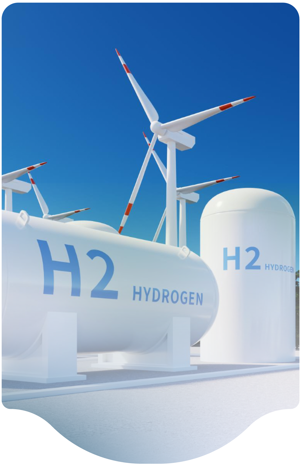
Reference NFPA 2 TIA 1783: As we continue the update for next submission of our hydrogen safety plan, we received this TIA about hydrogen releases from LH2 bulk storage tanks and potential impact on venting and plume dispersion. I understand this was rejected by the NFPA 2 committee, but I wanted to engage the HSP to get feedback if this is something we should consider in our design for site layout for our coming liquid hydrogen dispenser to support our project. We are going to raise this topic in our HAZOP, but we are interested if the panel has experience on how to best assess our bulk storage tank and vent stack configuration for the site before we go too far down any path.
TIA 1783 points out a valid concern about how to address the electrical classification zone around a liquid hydrogen system. The existing requirements specify 3' around the outlet of the stack for Division 1 and 25' around the outlet of the stack for Division 2 area. These distances are historical and date back to the 1960's. They are a "one size fits all" simple approach that is easy to implement. Most existing systems use these distances for hazardous area plot plans and equipment selection. However, the distances are conservative for some systems, but also may not be sufficient for larger systems with higher flowrates.
These classified areas apply both to the system itself (for leaks) as well as the vent system outlets. This becomes more complicated since leaks are not expected, but may occur. In contrast, vent stacks are frequently used and hydrogen is expected to be vented since that is the stack’s function. Therefore, vent systems should be designed to properly vent the hydrogen to minimize impacts to personnel, facilities, and the environment.
The currently adopted editions of NFPA 2 are minimum requirements, but best practice for vent stacks would be to follow principles in NFPA 497 to ensure that the specific system and stack classified areas are developed with the actual parameters based on flow, direction, height, physical design, etc. The expected vent flows should be modelled and the classified areas developed accordingly, while using current NFPA requirements as a minimum for both the system and vents. NFPA 2 will eventually be updated with a new table in the future that is similar to, but not the same as, the proposal in TIA 1783.
BACKGROUND:
A Division 1 classified area expects hydrogen to be present for some portion of the time during normal operation. A Division 2 area only expects hydrogen to be present under upset conditions. Since systems are designed not to leak, and since leaks are not normal, the area around piping/tanks/etc. is normally considered Division 2. However, in certain areas such as fill connections and vent systems, hydrogen gas releases are expected. Hence, these areas are considered to be Division 1. The 3' extent of Division 1 area is somewhat arbitrary. A fill connection might have a small release of hydrogen during disconnection. Alternately, a vent stack could release much more substantial volume of hydrogen: a relatively small volume from normal operations to a very large release from a pressure relief device. TIA 1783 was correctly noting that since relief devices are of known sizes, then the classified areas should be based on the actual modelling of the relief rates and not just depend upon the traditional 3' or 25' distances.
For example, if it is known that a production system will vent a quantity that will result in a cloud that is 50' radius every time that it shuts down, then the classified area(s) should be much larger than the prescribed area. Similarly, if there is a very large relief device that isn't expected to operate, but might reasonably operate during the life of the system, then a similar analysis should be done.
TIA 1783 tried to express this in a new table but requires additional dialogue and analysis. Documents such as NFPA 497 (as referenced in the TIA), and API Standard 520 can be used as a best practice to develop the appropriate classified areas based on release rate models.
Classified areas are often shown in 2-D on drawings, but they are more accurately portrayed in 3-D (e.g. a "sphere"). In these situations, the height of a vent stack is a key dimension to ensure that the hydrogen cloud, radiation, and overpressure don't significantly create harm, especially considering hydrogen’s buoyancy. A properly designed vent stack should ensure that the momentum from the release further facilitates the upward direction from buoyancy, thereby reducing the extent of the classified area in the downward direction.

