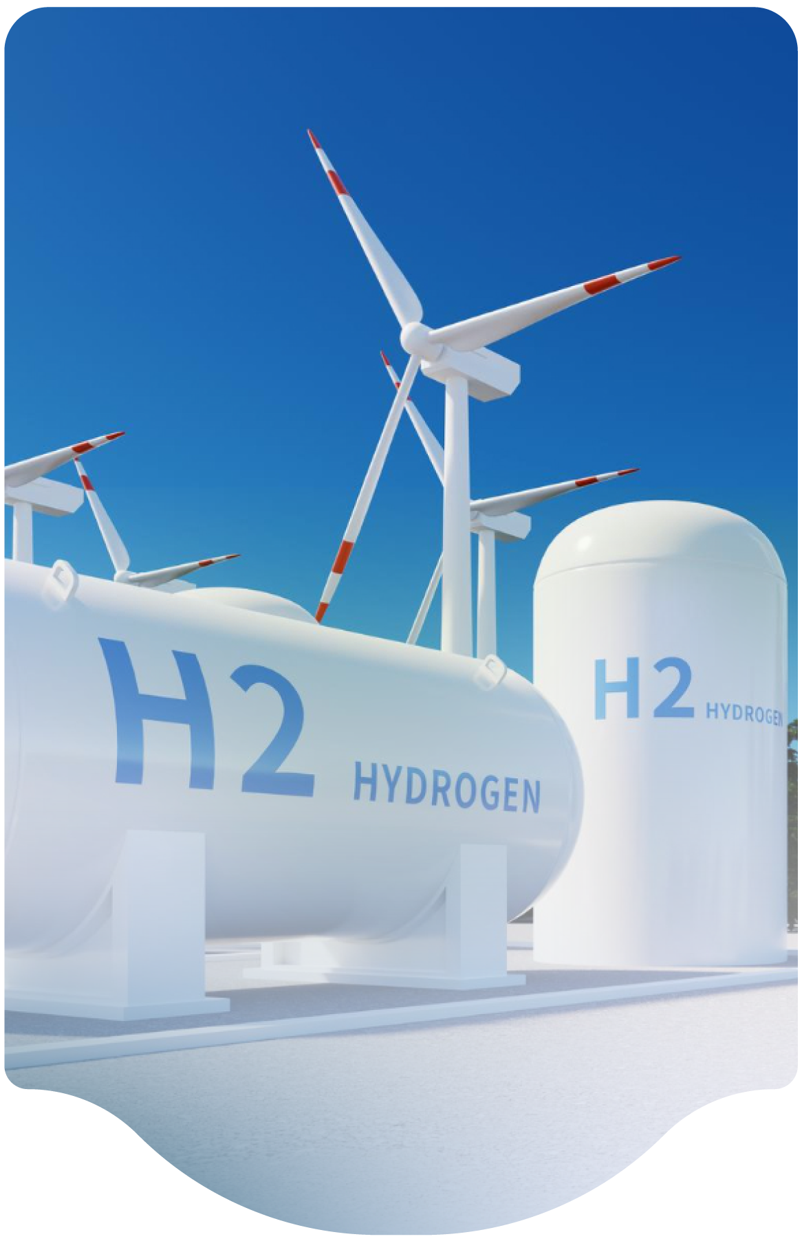
Hydrogen pressure vessels are typically isolated, not depressurized, during emergencies, with actions determined by hazard analysis.

Must a pressure vessel containing hydrogen be depressurized in an emergency?

In most cases, it is not necessary to depressurize hydrogen systems in an emergency. Pressure vessels are usually isolated in an emergency. The best actions to assure safety during an emergency should be identified during the hazard analysis.

FAQ Keyword
Submission Year
2023
Month
04

The requirement for TPRDs or PRDs on hydrogen storage vessels in mobile systems depends on jurisdictional regulations and performance testing outcomes.

In a mobile transportation hydrogen storage system, is it required to have a TPRD or PRD (Pressure Relief Device) on each vessel in the system?

Requirements for TPRD/PRD’s depend on the local regulations. Some jurisdictions require them, some do not. Others make them optional based on results of performance testing.

TPRDs are effective safeguards against tank overpressure during external fires if designed and installed per code, but their use requires consideration of system-specific factors.

What about TPRD (Temperature Actuated Pressure Relief Device)? Are they efficient to avoid storage tank explosion caused by overpressure during an external fire?

This is a complicated subject. Thermally activated pressure relief devices can be an important safeguard for hydrogen vessels if properly designed and installed in accordance with code requirement. Requirements vary globally and often depend on the type of vessel and its intended service (e.g. mobile or stationary). However, as with any device, TPRD’s offer both advantages and disadvantages. System design, vessel location, surrounding exposures, other vessel protection options, type of vessel, consequences of a large release, and probability of inadvertent release are just a few of many parameters that should be considered.

The criterion that sizes or defines the venting flow rate of an LH2 facility

What is typically the criterion that sizes or defines the venting flow rate of an LH2 facility, for example, emptying LH2 in x minutes due to a possible BLEVE (boiling liquid expanding vapor explosion) of the LH2 storage tank?

Relief device sizing for liquid hydrogen tanks follow recognized standards such as CGA S1.3. The sizing criteria include a worst-case scenario of an engulfing fire with loss of vacuum integrity.

LH2 tanks are unlikely to BLEVE due to the vacuum insulation outer jacket (usually carbon or stainless steel) preventing direct impingement of fire onto the main pressure vessel, as well as the internal cryogenic contents maintaining the inner pressure vessel walls at a cooler temperature until the contents have been relieved by the relief devices.

While not required by Code, nearly all LH2 tank designs follow a best practice of having at least one non-reclosing relief device to better empty the tank of its contents during a fire.

Pressure relief device settings for LH2 tanks

What are the typical criteria for determining the venting flow rates of LH2 facilities? For example, how quickly should LH2 be emptied in case of a potential BLEVE (boiling liquid expanding vapor explosion) caused by a fire near the LH2 storage tank?

There are several levels of documents which can be used to assist with the design, sizing, selection, and installation of the pressure relief device settings for LH2 tanks. 

Pressure vessel design codes, such as the ASME Boiler and Pressure Vessel Code will provide minimum requirements for design of pressure vessels (including LH2 tanks), relief devices, and relief systems. However, these codes will not provide the sizing criteria nor anticipate all of the potential demand cases that might be imparted upon a vessel. 

In the US, the model fire codes require compliance with NFPA 2, which then references documents such as CGA S1.2 and CGA S1.3 for sizing criteria. These documents have been customized by the industrial gas business specifically for cryogenic fluids such as LH2. API Standard 520 “Sizing, Selection and Installation of Pressure-Relieving Devices in Refineries” of is also a helpful document to provide additional guidance. 

For LH2 storage tanks, usually the highest process demand is an engulfing fire with a loss of vacuum insulation to atmosphere. This failure mode can result in additional heat flux from air condensation in the annular space which must also be addressed. 

It is not required to proactively vent the contents of an LH2 tank when exposed to fire. Relief devices are required to prevent the accumulation of internal pressure to unsafe levels. Within the ASME BPV, this is 121% of Maximum Allowable Working Pressure for scenarios involving fire exposure. It is common practice, but not required, that at least one device be non-reclosing (e.g. a rupture disc) for both managing the high flow required as well as to relieve the contents of the tank. Reclosing relief devices will maintain pressure in a fire and are more likely to lead to a vessel rupture if the fire ultimately weakens the pressure vessel.

LH2 tanks are unlikely to BLEVE due to the vacuum insulation outer jacket (usually carbon or stainless steel) preventing direct impingement of fire onto the main pressure vessel, as well as the internal cryogenic contents maintaining the main pressure vessel walls at a cooler temperature until the contents have been relieved by the relief devices. 

Isolating Energy Sources and Hazardous Substances Prior to Performing Maintenance

Guidance on isolating energy sources and hazardous substances prior to performing maintenance?

Safety codes globally have a requirement to provide a positive means to isolate energy sources and hazardous substances prior to performing maintenance. For gaseous hydrogen systems, methods such as a blind flange, a double block valve arrangement or a double block and bleed valve arrangement can provide that positive isolation.

Installing a blind flange requires breaking the supply line and inserting a solid insert that blocks the flow. The disadvantage of this approach is that it is more laborious than the other options and a method of isolation is needed to safely install the blind flange. The components involved are a lower cost than the other options but that cost is offset by the additional labor and system down-time required. For these reasons, they typically are only used for long term isolation.

A double valve arrangement is an effective approach that can be implemented quickly. A disadvantage of the double valve is that hydrogen may leak through the first valve and allow pressure to build between the valves without any indication. Aside from leading to a false sense of security, the pressure may also push its way through the second valve into the downstream plumbing and work area. While it may seem unlikely for two valves to leak, there sometimes is a common mode failure where both valves are damaged at the same time.

A double-block-and-bleed valve arrangement has a third valve to act as a means to vent, or "bleed" pressure between the two block valves. . In this configuration, leak through of the first valve cannot pressurize the second blocking valve, thereby eliminating the leak-through failure mode of the double block valve arrangement. For hydrogen systems, the outlet of the bleed valve should be routed to a safe venting location. A double block and bleed system can also be automated. In that situation the block valves are designed to fail closed and the bleed valve to fail open. Double block and bleed valves can also be used to safety depressurize and vent the downstream section prior to the isolation.

FAQ Keyword
Submission Year
2023
Month
05

Selecting and Installing Pressure Relief Devices

What are important considerations for selecting and installing relief devices for high pressure hydrogen storage blowdown?

Pressure relief systems may use reclosing devices like relief valves, non-reclosing devices like rupture discs, or a combination of both in parallel. Some systems may also be equipped with emergency blowdown systems that are operated by control systems. Selection of the proper devices is dependent on the system design and relative hazards. Variables that affect the selection include the type and size of vessel(s), location, pressure, and inventory.

The compressed gas industry is sensitive to the consequences of a premature activation of non-reclosing relief devices and the associated risk. More early activations have occurred than activations in real fire events. CGA S1.3, Pressure Relief Device Standards-Part 3-Stationary Storage, Containers for Compressed Gases allows for non-reclosing devices, but also recommends having a reclosing device as primary.

API 520, Sizing, Selection, and Installation of Pressure-relieving Devices Part I - Sizing and Selection, provides guidance on relief device selection and installation aimed at process plants. What might make sense in a process plant that has the potential for flammable liquid pool fires that might expose a gas storage vessel to an external fire for an extended period may not apply to other facilities.

Specific considerations not necessarily discussed in either CSA or API standards include:

· A prolonged fire exposure to a vessel may heat the vessel to a level where it is too weak to withstand the relief device set point. For this scenario, a reclosing device would not protect the vessel from reputing whereas a non-reclosing device might.

· Rapid depressurization of a vessel containing high pressure hydrogen can lead to cold temperatures at the nozzle of the vessel and to a lesser extent to the entire vessel. In an external fire case, the cold temperature would likely be mitigated. However, cold temperatures could develop in non-fire venting cases. For metal vessels, the strength of the vessel increases as the vessel cools, thereby reducing susceptibility to failure. But if the vessel is made from carbon or low alloy steel, the vessel may become vulnerable to brittle fracture.

· A depressurization with a non-reclosing device may form a large vapor cloud. Non-reclosing devices are typically larger and depressurize the vessels at a faster rate. There is a high probability that a vapor cloud will form and find an ignition source, resulting in a deflagration. The resultant fireball and overpressure can cause damage and injure people.

Sizing Pressure Relief Devices

For fixed equipment in gaseous hydrogen storage service, should we use the API or the CGA method to size a relief device?

API 520, Sizing, Selection, and Installation of Pressure-relieving Devices Part I - Sizing and Selection, was written for use in the process industries in gas and liquid service.

CGA S1.3, Pressure Relief Device Standards-Part 3-Stationary Storage Containers for Compressed Gases was written for fixed equipment in gas service.

Which standard to use depends on the choice by the owner/designer considering regulations that may apply. In the USA, the API standard is used most often in process plants where local regulations for relief valve sizing usually do not apply. For other industrial facilities and for commercial and residential facilities, regulations frequently apply. The CGA standard is more often referenced in regulations.

Submission Year
2024
Month
02

Pressure Relief Valve Orifice Size

What is the basis for the required relief valve orifice size in CGA S1.3, Pressure Relief Device Standards-Part 3-Stationary Storage Containers for Compressed Gases?

Equation 6.3.1.1 in CGA S1.3 is based on modeling to API methods described in: Heitner, T. Trautmauis, and M. Morrissey, “Relieving Requirements for Gas Filled Vessels Exposed to Fire,” 1983 Proceedings-Refining Department, Volume 62, American Petroleum Institute, Washington, D.C., pp. 112-122.

This method considers the transient nature of the vessel warming in combination with the venting of the vessel. It also includes the inherent delay in the gas temperature increase over time. This approach is used as the basis for CGA S1.3 and has proven valid for industrial gas and related vessels.

Submission Year
2024
Month
02

Inspection, Testing

What are the typical inspection/testing requirements of the safety circuit (rupture disks / relief devices)?

An annual inspection of safety devices is recommended. Testing requirements will be based on the type of device and a quantified risk analysis. Typical replacement or function testing of relief valves is between 5 and 10 years depending on the application within the industrial gas industry. Rupture discs are not tested but are frequently replaced on an interval based on manufacturer recommendations and a mechanical integrity program established by the operator. For transportation applications, rupture discs are usually replaced at vessel requalification at either 5 or 10 years depending on test method.

Submission Year
2023
Month
03
Subscribe to Pressure Relief Devices
We are professional and reliable provider since we offer customers the most powerful and beautiful themes. Besides, we always catch the latest technology and adapt to follow world’s new trends to deliver the best themes to the market.

Contact info

We are the leaders in the building industries and factories. We're word wide. We never give up on the challenges.

Recent Posts