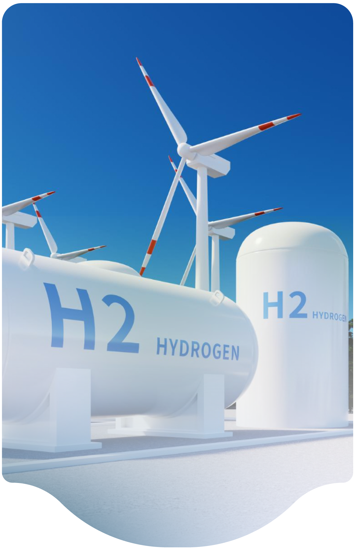
Leak detector requirements for hydrogen systems vary by application and design, with refueling stations typically mandated to have detection systems.

What are leak detector requirements for hydrogen refueling stations, production assets, pipelines, etc.?

Leak detection system requirements depend on the system design and applicable codes. The
appropriateness of detection equipment depend on many factors, including the type of system,
application, location, and probability of leaks. For example, hydrogen refueling stations are required by
code to be equipped with leak detection systems.

FAQ Category
Submission Year
2023
Month
04

Hydrogen Temperature Mixing

Are there specific hazards to consider when mixing varied H2 temperature streams (gas and liquid) at a pipe junction, considering the following design features? (1) Cold hydrogen at the pump discharge is directed along two paths. One path uses ambient heat to warm the hydrogen, while the other path bypasses the heater to remain cold. Valves in each stream then adjust the flow split to achieve a controlled hydrogen mix temperature when the streams are recombined. The temperature-controlled stream is then directed to a dispensing station. (2) The hydrogen chilling system combines the cold hydrogen fluid with warmer hydrogen compressed gas to achieve the temperature necessary to provide a fast-fueling experience. The system will monitor the chilled fluid temperature and the vaporized warm gas and combine their streams using mixing valves and controls to provide -40 deg C° gas to the dispensers.

This is a fairly common arrangement and can be acceptable if properly designed. Some considerations:

  1. The main concern is low temperature downstream of the mixing point, in case of mixing valve failure. Perform a LOPA (layer of protection analysis) on the safeguards. A shutdown table showing the action of each shutdown would help with understanding the layers of protection. The primary means of temperature control could fail if the temperature control valve fails open or if the sensing circuit fails high. The safeguards can then be evaluated to protect downstream equipment from getting too cold. The layers of protection should include two independent means of low temperature control: detection and shutdown. For example, the safeguards could consist of both stopping the pump and shutting an emergency AOV. 
  2. Another low-temperature concern arises when the storage vessel AOVs are UPSTREAM of the normal temperature element (TE) to detect low temperature gas past the vaporizer. This is less of a concern for an ambient vaporizer since they can't fail "suddenly", but still it's best practice to install a TE upstream of any equipment that could experience brittle failure. It's possible that the buffer vessels will be stainless steel (or other material capable of low temps), but they are most likely carbon steel with a lower temperature limit of -20 deg F° or -40 deg F°. In this case, it is recommended that a TE be installed upstream of this connection. The temperature setpoint should be verified to be no lower than the rating of the vessel materials. It might also be possible (but unlikely) to backflow from the cold line if there is a leak on the storage vessels. The TE might protect against backflow depending on its operation. 
  3. It might be possible to block in the vaporizers from the relief valve downstream. Verify that there is a relief valve that protects the vaporizer from a blocked-in liquid situation between shutoff valves and/or check valves. 
  4. There could be sections of line on the vaporizer bypass where cold gas/liquid could be trapped between valves if closed when cold. For example, the double block and bleed valves. Verify that these lines can't be overpressurized in a trapped cold gas/liquid scenario. Install a relief valve(s) where needed or remove some of the valves to reduce the possibility of trapped product.
  5. Failure of controls or control valves could "deadhead" the pump, leading to trapped liquid and/or an operating pump being blocked in. This could result in a relief valve lifting and/or an overpressure situation if no relief valves are present. Verify the intent of the AOV operation when the pump is running, verify that there are sufficient relief valves on the pump discharge, and determine if there is a blocked in or deadhead situation. 
  6. Even if there is all stainless steel construction downstream, the dispensing hose (-40 deg F°) or the vehicle itself (-40 deg F°) still must be protected from cold temperatures.


FAQ Category
Submission Year
2024
Month
05

Process Safety Management

Does PSM apply to hydrogen fueling or refueling stations with more than 10,000 lb. of hydrogen onsite? Some have suggested that H2 fueling stations are exempted, but that seems incorrect.

There is no generalized exception for hydrogen fueling stations.  However, PSM is intended for employee protection. It’s not intended for retail operations or customers. Through paragraph 1910.119 (a)(2)(1) of the regulation, PSM exempts retail facilities. Some may use this exemption as a means to exclude H2 retail fuel sites from PSM.


Fuel stations that are non-retail, such as those that might supply forklifts, transit buses, or an in-house fleet of trucks, would still require PSM compliance if the 10000 lb. threshold is exceeded. Fuel stations that sell to the general public, such as light duty vehicle stations and truck stops, are retail facilities and may qualify for an exemption. There is no defined term for “retail,” so some subjectivity exists with regard to the type or amount of retail activity that would be required for this exemption.  It is not directly applicable, but parallel language in the EPA’s Risk Management Program (RMP) regulation states that a facility must be at least 50% retail to qualify for a retail exemption.


While it’s possible to avoid PSM regulation by maintaining total site inventory below 10000 lbs. and/or applying a retail exemption, the principles of PSM are sound. There is value to adopting the PSM principles to all systems and it’s  a best practice to apply to all hydrogen systems regardless of quantity or exemption status. However, many want to avoid the regulatory risk of additional scrutiny and being subject to audits. Most fuel stations to-date have managed to stay below the 10000 lb. threshold, but it’s expected that station size will grow as the market for heavier vehicles develops.


FAQ Category
Submission Year
2024
Month
05

Tank Filling

How can I calculate how much gaseous hydrogen storage is required at pressure Y psi to conduct a certain number of vehicle fills to 350 bar or 700 bar?

This is not an easy question since many factors influence how much hydrogen can be transferred from one vessel at a higher pressure to another one at a lower pressure and the rate at which it can be transferred. The pressure in the higher vessel will fall while that in the lower vessel will rise as gas is transferred, so the flow rate will typically slow down and eventually stop as the pressures equalize. Fueling protocols have important upper and lower bounds on the flow rate or pressure change rate that is allowed when filling a vehicle. The SAE J2601 family of standards detail those rates and ending pressures.  Most hydrogen dispensers use a cascade method of fueling (switching between multiple supply tanks) to maintain the desired flow rate and maximize the amount of hydrogen that can be supplied. As a general rule, a higher percentage of gas can be transferred from the supply tanks when filling lower pressure 350 bar tanks than higher pressure 700 bar tanks.  Similarly, as storage pressure Y psi is increased, a higher percentage of the gas will be usable for either fill pressure.


The density of hydrogen does not vary linearly with pressure since it’s not an ideal gas. For reference, the density of gas at 350 bar is 24 g/liter and at 700 bar is 40 g/liter. Thus, doubling the pressure only results in a 60% increase in storage volume. For this reason, 700 bar vehicle tanks are rarely filled from a single tank and either use multiple supply tanks in a “Cascade” type system or are direct filled from compression systems. 

FAQ Category
Submission Year
2024
Month
04

Boil off Gas at Fuel Stations

What is the best approach to handling the boil-off gas from a liquefied hydrogen tank at a fueling station? What are the safety precautions?

If liquid hydrogen usage is sufficiently high at the fueling station, there may be no need to vent any boiloff generated from the LH2 storage tank. Boil-off gas should be minimized through system design, but where needed, the boil-off hydrogen along with any other hydrogen released must be vented through a local vent stack which is constructed to safely vent the hydrogen in accordance with CGA G5.5 and NFPA 2. These standards anticipate the possible ignition of hydrogen in a vent stack and have provisions for that to happen safely. If economical, the boil-off gas can also be captured by using a gas compressor to store the gas for dispensing into vehicles.

FAQ Category
Submission Year
2024
Month
04

Dispensing at Fuel Stations

Is there a separate standard that governs dispensing of liquid hydrogen at a liquefied hydrogen fueling station?

In the U.S., liquid hydrogen fueling stations and dispensing equipment are addressed within NFPA 2, Chapter 11. Dispensing is covered within Section 11.3. When liquefied hydrogen is used as the supply for high pressure gaseous fueling, then Chapter 10 of NFPA 2 would apply.
ISO standards are also being developed for global LH2 fueling protocols.
 

FAQ Category
Submission Year
2024
Month
04
Subscribe to Fueling Station
We are professional and reliable provider since we offer customers the most powerful and beautiful themes. Besides, we always catch the latest technology and adapt to follow world’s new trends to deliver the best themes to the market.

Contact info

We are the leaders in the building industries and factories. We're word wide. We never give up on the challenges.

Recent Posts